
The Ghost in the Shell (Custom Gun)
Designed by John Pope and Howard Scott for Howard Scott (Team NightForce)
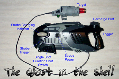
The Ghost in the Shell was an idea Howard had two years after his friend, Kyle, died. He wanted to use the guts out of Kyle's old gun to create the first custom gun for Team NightForce. The shell of the gun is a water gun purchased from Wal-Mart. All the water guts were pulled out of it. After a lot of redesign work on extremity placement, the guts of Kyle's ESS gun were placed in the shell. A rechargeable 7.2v battery was placed in the water tank. A recharge port was installed in the large refuel cap. A "pillow switch" push button was installed as a trigger. The ESS single shot/duration shot switch was redesigned by John Pope into the pump action of the old water gun. The forward position is Duration Shot; the back position is single shot. The internal switch is wholly constructed by John. The hit indicator light on the ESS gun was pulled into the sighting assembly on the front of the gun. The lens/emitter assembly is a custom unit designed and constructed by John. Just below the emitter assembly is a Sunburst mod. Power is provided by a closed AA battery system separate from the gun power. The charge indicators are two LEDs placed on either side of the front of the gun. As the strobe charges, these gems slowly begin to glow. A separate trigger actuates the flash. As soon as it discharges, power is immediately applied to the capacitor to charge it again. This gun is awesome!
Oh. Here's the picture of it.
The New Lightweight Bases and Flags
Playing in the dark like we do, we have to use flags and bases that are visible at night.
All PVC is 3/4", although you will need two PSI thicknesses... be careful about which you use where.
All items were purchased from Lowe's because they are right around the corner.
What you'll need for a single base:
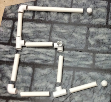
- One 5' piece of 480 PSI PVC cut into:
- Six 6" pieces
- One 13" piece
- Two push-on end caps (not the threaded)
- Two 90º elbows
- Two 90º Tees
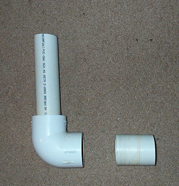
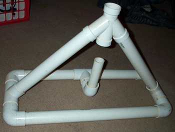
- One Three-Way Side Outlet Elbow (the funky thin g in the middle of the picture)
We do not use any glue to secure our pieces, but you certainly could. The finished "foot"looks like this
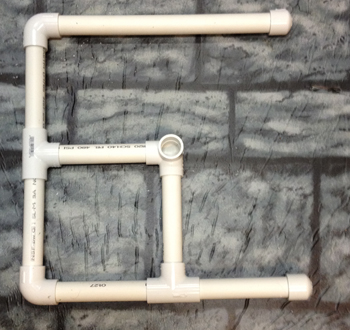
That's the foot of the base.
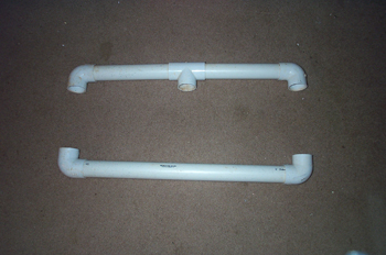
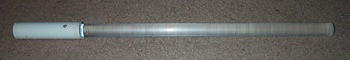
The Base Column and the Flag Baton are simply lengths of 200 PSI PVC with couiplers and the LED wands. They made using the same method, but we use a 2' base column and a 1' flag baton:
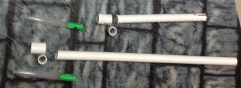
What you'll need for a single baton:
- One 12" piece of 200 PSI PVC (note the 200 PSI!)
- One pipe coupler
- One spacer cut from the scrap of 480 PSI PVC
- One Energizer LED Wand
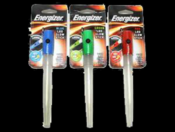
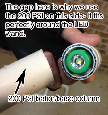
I like these because of the push-button and the replaceable batteries (the wand comes off and the LED insert comes out to gain access to the batteries, three button cells). These come in three colors, red, green, and blue. My ESS teams can be divided into red, green, and yellow. OK, so the yellow team has to use the blue wand. It all works out. Also, the 480 PSI spacer and the 200 PSI baton work perfectly with the width of the colored handle of these. I recommend them highly.
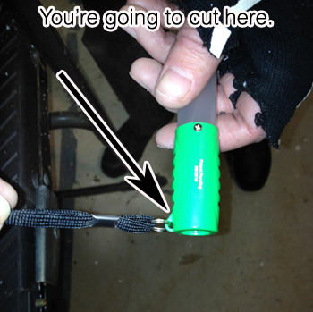
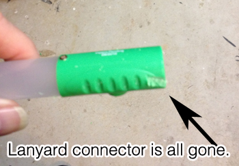
First, you have to cut the lanyard connector off the LED wand.
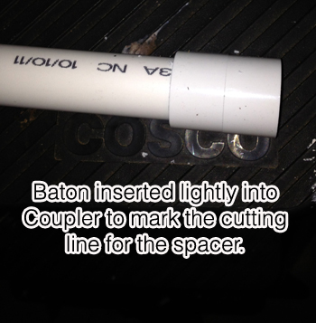
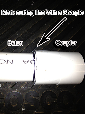
Next, you will cut the spacer from the 480 PSI PVC. Lightly push the coupler onto the 480 PSI pipe, and mark the point where the coupler ends once the pipe is fully inserted.
![]()
Cut the spacer and put it aside for a moment.
Next, cut the 12" baton from the 200 PSI PVC. Since this is a baton, and not the base, I wouldn't go much longer on this piece of PVC. People will be running with it, and this will have the 6" of LED wand sticking out of the top.
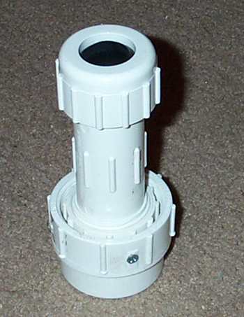
Now to construct the baton:
![]()
Push the spacer into the coupler. You can smack it really hard on a concrete floor, or brick wall, to push it in and keep it there, or you can glue it. We don't glue anything, just in case we make a mistake.
At this point, you would turn the colored LED wand on either solid or flashing if you were playing a game. I use solid light for the base and flashing light for the flag.
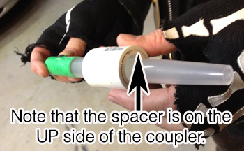
Insert the LED wand into the coupler/spacer unit so that the spacer is on the up side of the coupler.
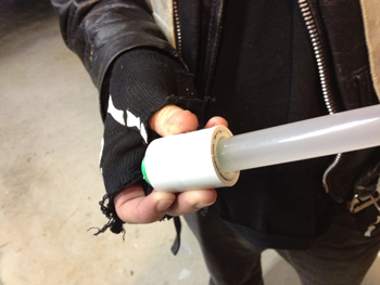
Push the wand into the coupler, and you will feel it click into place.
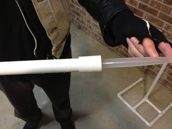
Push the 200 PSI baton into the coupler to complete construction.
Use this same method to construct the base. We use a 2' piece of 200 PSI PVC for the column, but this length is up to you and how tall you want the completed base/baton to be.
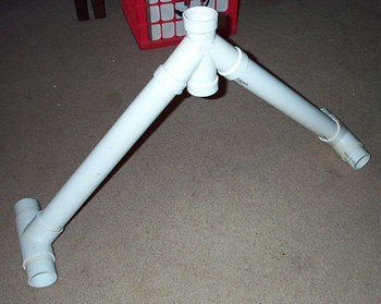
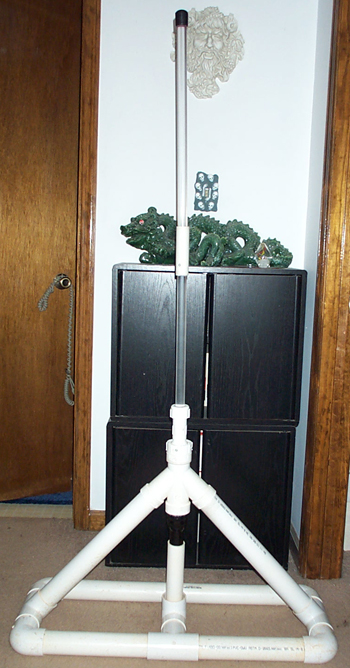
To complete construction of the base, place the completed base column (the taller of the two batons) into the side outlet elbow in the center of the completed foot:
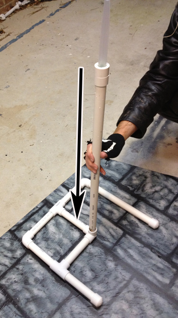
You'll want to push down pretty hard. This piece is not supposed to come out during game play once the wand is turned on and in place.
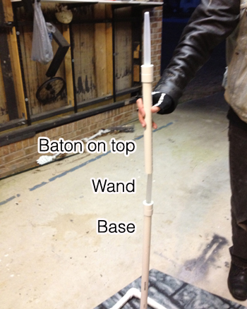
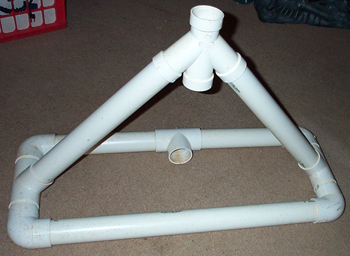
The baton simply sits on the coupler/spacer of the base, using the secured base wand as a slip post.

Our two new bases. We have since fixed the issue with the heights being different. The lean is not something I can fix, yet.
The Way-Too-Heavy Bases and Flags:
The Strobing Flag
This is just in case you want the full heavy industrial look. We used them forever, and they were amazingly sturdy, but they were huge, not very storable, and a pain to carry and transfer from site to site and between games.
What you'll need:
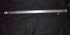
- One six-foot long 1" diameter clear acrylic staff
- One 1.5 inch diameter folding chair tip
- One LED circuit (click here to go to ChemLight)
- Some duct tape
- Scrap soft foam
Construction:
- Cut the rod into three 2' sections and use one of the pieces with the rounded end for the flag (we made two flags and one base from one staff).
- Using some ultra-fine grit sandpaper, "frost" the rod thoroughly and evenly.
- Drill into the center of the flat cut end approximately half an inch with a 3/8 inch bit. This hole is to fit the LED. Test it to see how deep it really needs to be.
- Cut the duct tape into 4-5" strips, then cut those in half lengthwise. Wrap the tape around the cut end of the flag rod, leaving about 1/8" at the top clean. Wrap enough tape around the end to keep the 1.5 inch chair tip in place. It needs to be removable. You can see the duct tape on the left side of this image.
- Once the chair tip fits comfortably around the duct tape, cut a small piece of the soft foam to fit into the end of it. This is now your protective cap for the flat end of the rod.
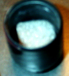
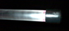
- Place one LED circuit into the drilled hole. Carefully place the cap on to make sure it fits without cracking the LED (I broke four or five of these getting the safety factor right). Then, remove the cap, turn the LED on, replace the cap, and find a dark place to see the wonder of your new strobing flag!
We get more than 24 hours of constant use out of these LED circuits. That's about 6 nights of play. The batteries can be found fairly cheaply online.
The Flag Base
We needed something portable, but sturdy enough to hold the flags stable. These are made entirely from PVC.
All PVC is Schedule 40.
For ONE Base, you will need the following:
- One 10’ length of 2” Pipe
- One 2’+ scrap of 1” Pipe
- One 1’+ scrap of 1.5” Pipe
- Five 2” 90° Elbow Joints
- Three 2” T-Joints
- One 2” Double Wye Joint
- One 1.5” End cap
- One 3” to 2” Reducer with Threads
- One Compression thingy with threaded caps on both ends and black rubber washers
- One 24” section of Lucite staff (the one with two cut ends)
- Four .5” sharp wood screws (3/32” diameter)
- One Maglight brand 3 D-cell flashlight
- All-purpose PVC glue
For ONE Base, you will need to cut the pipes above into following:
- Five 3” lengths of 2” Pipe
- Two 18.5” lengths of 2” Pipe
- Two 13.5” lengths of 2” Pipe
- One 29.5” length of 2” Pipe
- One 7.5” length of 1.5” Pipe
- One 5” length of 1” Pipe
Flashlight Support:
- Glue End cap onto one end of 7.5” X 1.5” Pipe
- Glue End cap of Step 1 into one of the Elbow Joints. Be sure this piece is vertical.
- Put glue away.
- Insert 3” length of 2” Pipe into other side of Elbow Joint.
This completes the Flashlight Support.
Upright Assembly: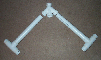
- Insert 18.5” lengths into the 45° angles of the Double Wye Joint
- Put a T-Joint on the exposed ends of the 18.5” lengths
- Insert 3” lengths into the four connections of the T-Joint.
This completes the Upright Assembly. Set this unit to one side
Side One Assembly:
- Put two 90° Elbow Joints on the 29.5” length of 2” Pipe
This completes Side One Assembly
Side Two Assembly
- Insert the two 13.5” lengths of 2” Pipe into opposing ends of the remaining T-Joint
- Put a 90° Elbow Joint on opposite ends of above unit
- Insert 3” length of 2” Pipe into Elbow Joint assembly from Flashlight Support
This completes Side Two Assembly
Building the Stand
- Line up Elbow Joints from Side One assembly with 3” connectors of the Upright Assembly. Squeeze them together.
- Line up 3” connector from Flashlight Support with open T-Joint of Side Two Assembly. Squeeze them together.
- Line up Elbow Joints from Side Two assembly with 3” connectors of the Upright Assembly. Squeeze them together.
This completes the Stand Assembly
Base Staff Assembly
- Insert one end cap from Compression Joint into 3” end of 3” to 2” Reducer
- Drill 3/32” pilot holes through both sides of both pieces
- Screw two screws into the pilot holes, taking care not to screw into the threads of the Compression Joint.
- Wrap a length of 2” wide Duct Tape around the cut end of the 4’ piece of Lucite.
- Using the same drill bit, drill pilot holes through the 5” length of 1” pipe at the 1” mark.
- Slide the 5” length of 1” Pipe to just cover the Duct Tape with the pilot holes over the Duct Tape.
- Using the same drill bit and the pilot holes in the 1” Pipe, drill pilot holes into the Lucite
- Screw the remaining screws through the 1” Pipe and into the Lucite.
- Slide the uncut end of the Lucite into the unmodified end of the Compression Joint, then through the modified end, allowing about 4” to extend through.
- Tighten both ends of the Compression Joint to grip the Lucite firmly.
This completes the Base Staff Assembly
The Battle Boxes
We discovered several years ago that each standard footlocker trunk holds 14 standard unboxed guns wonderfully! Recently, after converting all our headsets to the Velcro Strap Mod, we realized we now had a way of storing our headsets in the lid of the trunks. Some sticky-backed Velcro and ten pop rivets later (the sticky part of the sticky-backed Velcro didn't hold), we have the trunks converted into ESS Battle Boxes! Both fit into my car's trunk.

Trunk 1, fully loaded with 14 guns- 7 red, 7 green. Trunk 1 also carries the base pole and strobe flag. Because of this, Trunk 1 must be carried to every game.

Trunk 2 fully loaded with 14 guns- 7 red, 7 green.
Each Battle Box has its own Accessory Kit.
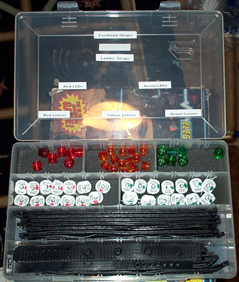
Box 1 is the Master Box and includes 14 Ladder Straps, 14 Forehead Straps, 13 red LEDs and 13 green LEDs for the Strobe Flags (in case the current LED dies), and extra red, yellow, and green lenses for the Team Mod.
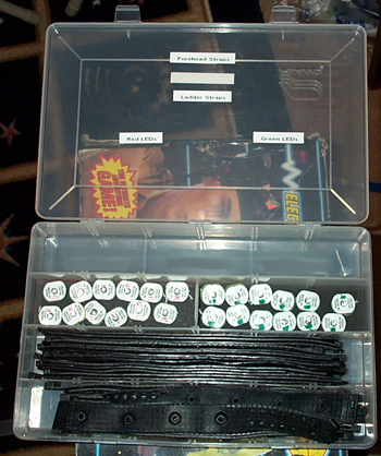
Box 2 is the Slave Box. Its contents are almost identical to Box 1, but it includes no Team Mod lenses.
All material © 1997-2005, Chaos Enterprises, Inc.